Search This Blog

Showing posts with label raspberry pi. Show all posts

Friday, July 24, 2020

Updating the RPI NAS

The RPI NAS that I had built a nice white wood box for has a new home. After finding a design for rack mounted raspberry pi, I knew I must have it. I came across the following design which holds 2 pi's:
https://www.thingiverse.com/thing:3541225

I already have one running openhab and then having a second running openmediavault and pihole, this was perfect. I also have a 3d-printer, so no prob! Well it took a few months for parts to come in and my 3d printer kept breaking. But its finished! Since this picture was taken I have put the 2nd raspberry pi in the setup, everything seems to be running smooth.


If you are curious about the code running the OLED displays. Follow this adafruit blog post, I have raspbian OS launch a python script as a service on boot.

https://learn.adafruit.com/adafruit-pioled-128x32-mini-oled-for-raspberry-pi/usage

Wednesday, January 8, 2020

RPI NAS

Started a new project over Christmas break. Using some old parts and newish ebay components I was able to setup a minimalist NAS, if that's a thing lol. 

Parts list:
- Raspberry pi 1 model b w/o ethernet, this might be the 256mb model aswell 
- enc28j60 ethernet module
- 4 port usb hub
- 2 usb hard drives
- 2 old usb thumb drives
- 12v power supply 
- 5v step down regulator

If you kind of understand what's going on with this project, then you're probably pretty perplexed. Why use a pi without a network interface for a project that needs ethernet? Why use a 12v power supply when everything requires 5v? Why didn't you use a powered usb hub? The simple answer is, this is what I had on me and I didn't want to spend the $$$. So there were many inefficiencies to get this to work. I used a $2 spi ethernet module that the latest Raspbian os supports, used a $1 voltage converter to step the 12v down to 5v, and spliced the non-powered usb hub to pull power from a separate source. 


After soldering it all together, making a wood case out of scrap wood, and setting up the pi with samba. It works! But it's slow as fuck. Pretty much can only store documents on this punny beast, pictures and large files take to long to transfer to be useful. Pretty sure the issue is the ebay ethernet adapter. If I switched out the pi with a rpi 3 or 4, I think this would function alot better. 

Thursday, November 21, 2019

Adding Wifi to a Dumb RGB Light Bulb

Many years ago I had bought a RGB led bulb off amazon to try out, when there really wasnt a smart bulb market. After collecting dust more many years it has found a use! I moved into a new apartment and the foyer light was burnt out, i tried like 4 different LED and non-LED bulbs, and this cheapo RGB bulb was the only one that worked.

Problem with this bulb is when you turn it on, it comes on red and you have to use the IR remote to change it to white....  I really dont want to use a remote, so time for an upgrade. Luckily I had a ESP micro laying around, specifically a Wemos D1 mini. This is also a great opportunity to add another device to my home automation system. The plan is to have this device communicate using MQTT to a raspberry pi running Openhab.

Steps to put a new brain in the light bulb:

  • Pull off plastic cap, pry original PCB from aluminum housing(just glued down with some sort of thermal glue).
  • De-solder the original IC, oscillator, and IR receiver led.
  • Wire the original DC power wires into the wemos and add new power wires between wemos and led board.
  • Add 3 wires between wemos and led board for red, green, and blue control.
  • Program custom code(Github link). I used the Arduino IDE and the following libraries:
    • ESP Wifi
    • MQTT
    • OTA downloads


Board stack showing wemos under RGB led board.

Wires soldered onto the pads of the existing IC.
Update: In retrospect I should have just used the really nice tasmota software available for free and created a custom config.

Thursday, September 3, 2015

Integrated the electronics panel with the brew cart

For the most part the pi and the electronics are now working with the screen and switches. So I installed the panel in the brew rig and got it setup on the parents WiFi. Slow progress but at least it's progress!

Saturday, April 25, 2015

Consolidating the homebrew electronics

About half way through the process of combining all 3 electronics boxes into one panel. Also adding WiFi and a webserver for remote temperature monitoring!

Saturday, February 8, 2014

New PCB for the brew computer

Recently upgraded the beer computer with a new custom pcb designed in eagle cad. The original board had turned into a rats nest after adding modifications over and over. The new board now allows all the breakout boards to easily plug in and is a smaller form factor. One difference is the mosfet to control the solenoid for the gas burner was moved off this board.

Original Board(The rats nest)
The new un-populated pcb.
Finished board!

Sunday, October 27, 2013

Updates to Beer Brewing Computer

I had to open the case up to make some changes to the beer computer. Snapped a few pictures of the internals while I had it open.
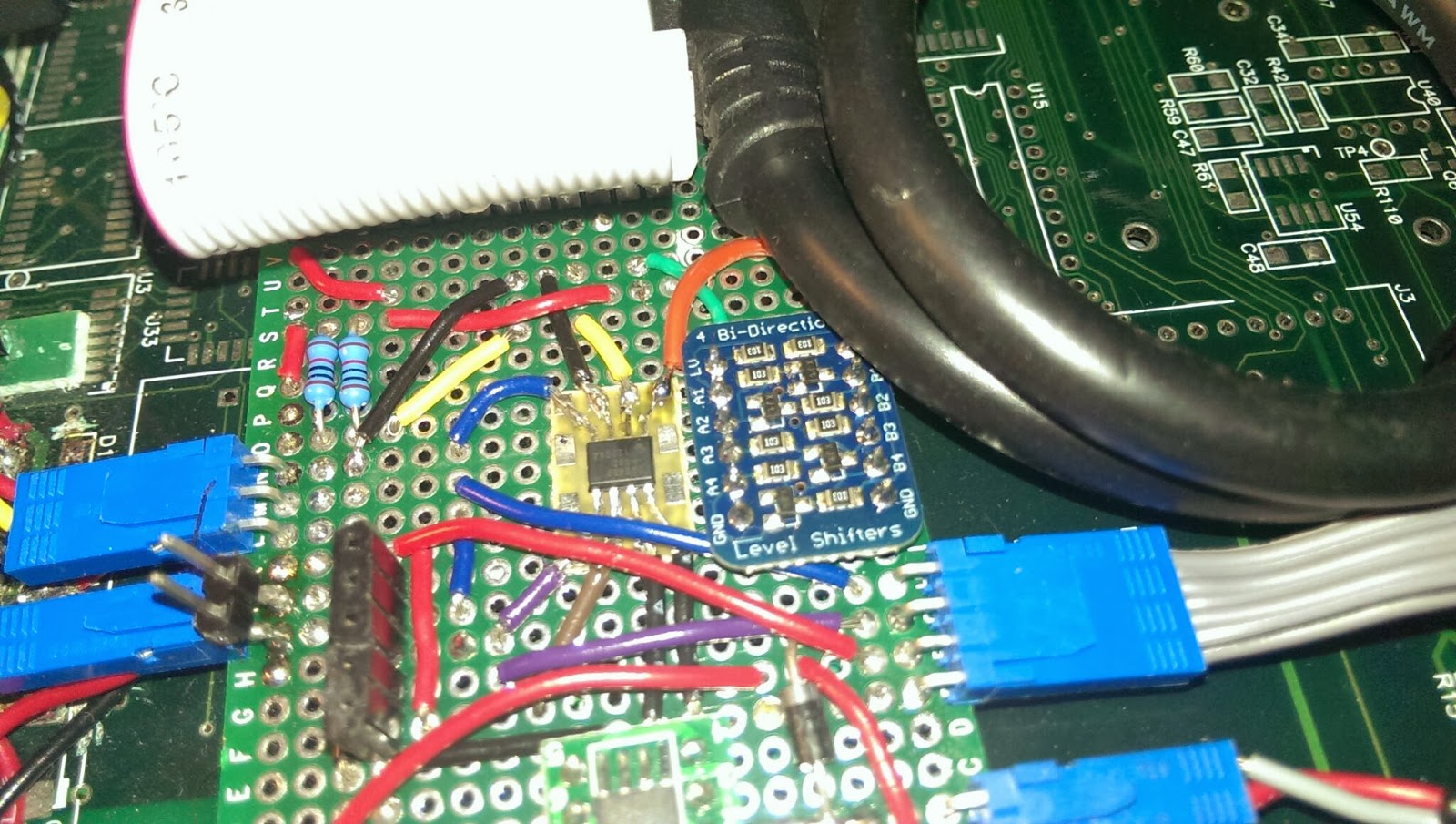
The blue board has a ds1307 rtc on it. The green 8-soic to 8-dip board has a mosfet to control the 12v output.
Adafruit's bidirectional logic level shifter. This is used to convert the 3.3v logic level i2c lines to 5v for all the other devices on the i2c bus. 
Adafruit's i2c ADC breakout board
Raspberry PI model B with a heat sink! Has some overheating issues when the outdoor temperature was over 100 F.
The connectors mounted on the rear of the box. USB, HDMI, 3 1-wire connectors, the midi style connector providers the 5v and 12v input.

Saturday, October 12, 2013

Beer Brewing Computer


  1.       This is a project I have been working on for the past couple of months. I needed a way to keep my beer boiling at a certain temperature for an extended period of time. What better then to use a computer to do that for me, so I don't have to physically throttle the propane burner. This brew computer is raspberry pi controller and uses multiple ds18b20 1-wire temperature sensors to monitor the beer temperature. Then using the RPI GPIO I can toggle a mosfet to control a solenoid valve on the gas line.

    Prototype

    Laser cut front panel to identify the potentiometers. I wanted some physical interface to set the temperature. 

    Custom graphical interface which is done in python. These python scripts are ran on boot up, so no need for an X server.
Loading